Misc Projects : 500mA 5-channel RGB LED Controller / Driver
This project is a revision of my previous High Power RGB LED Controller. It corrects several bugs in the software, facilitating faster color updates from the computer (~250fps), allowing experimentation with fast, but 'smooth', color changes, and implements 2-way communication with the microcontroller.
Additionally, and more significantly, the hardware has been redesigned to use switching current regulators (National Semi. LM3402) for accurate LED current control, and high efficiency. One board includes the PIC microcontroller, USB communications, and one TLC5940. This handles computer communications and 12-bit pulse width modulation (PWM) intensity control for 15 channels. Another board has the LED regulators, 15 in total, to provide 500mA to each of 5 Lamina Atlas RGB LEDs. This eliminates any need for current limiting resistors, allowing for accurate balance between the colors within an LED, and between LEDs. The result is that little color and white calibration is required, which, without more equipment, was an inexact science.
LED Controller
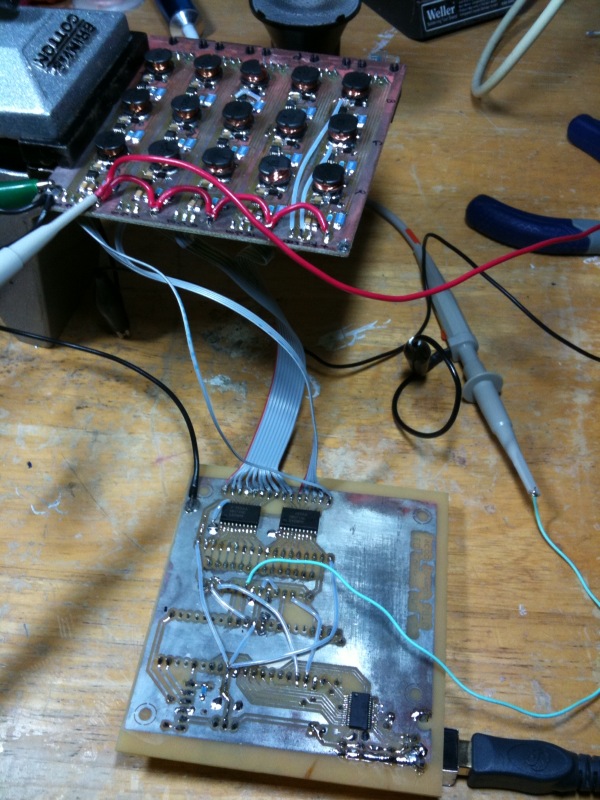
The controller implements communications with the computer by USB, using an FTDI 245RL chip. This is interfaced to a MicroChip PIC16F887A microcontroller, which handles the timing and communications with a TLC5940 LED driver for 12-bit PWM regulation of each of 15 color channels. Finally, this board inverts the open-drain PWM output of the TLC5940 to logic levels for input into the driver board.
The PIC runs at 8 MHz. The oscillator output on this chip is at OSC/4, which, at 2 MHz, drives the grayscale (GSCLK) counter of the TLC5940. 12-bit intensity values are output by the TLC5940 by turning the output on for a portion of each 4096 pulses, resulting in a PWM frequency of 500 Hz. (Actually, 3 PIC cycles are lost each block of 4096 to pulse BLANK, so the frequency is just under 500 Hz.) 500 Hz is fast enough that it should never be visible. It is also slow enough that the switching regulators can run at slower speeds (500 KHz, currently), at which they are more efficient.
At least for now, the microcontroller is underutilized, with firmware sufficient only for relaying messages to and from the computer. Most logic, such as flashing or slewing between colors, is implemented in software (Python) on the computer. It is easier to test new functionality on the computer than repeatedly update the firmware. Functionality that requires better time control, such as music synchronization, will be implemented on the microcontroller, but this need hasn't arisen yet.
Though little used, the microcontroller can't be omitted. The TLC5940 does require careful timing for pulsing BLANK every 4096-ticks, and synchronization of SPI communication so that commands don't overlap a BLANK cycle. This is difficult to get right without a dedicated microcontroller.
This board accommodates in-circuit debugging (ICD). I use a PicKit 2 programmer/debugger. Unfortunately, the debugger requires Windows and MPLAB (I've not tried wine.). Programming works great from Linux, using PK2CMD, available from Microchip at the preceding link.
| Schematic | Board Layout | Eagle | Eagle |
|---|
500mA 5-channel RGB LED Driver
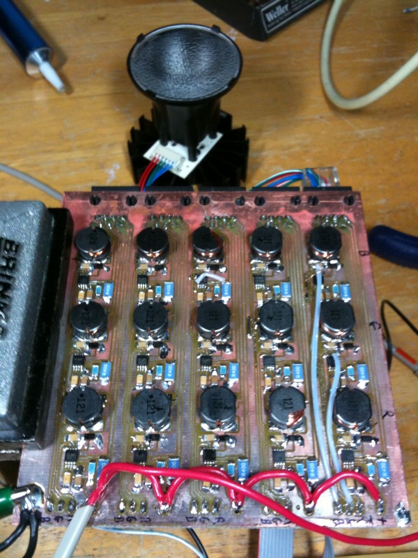
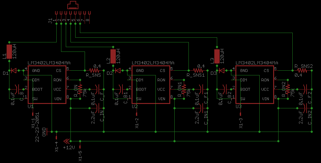
The driver board consists of 5 banks of 3 LED drivers (15 in total), one for each channel of each RGB LED. These utilize the Nat. Semi. LM3402 constant current buck regulator. Each driver accepts a fast PWM signal for modulating intensity for full spectrum color output. The use of switching regulators for current regulation results in high efficiency and, consequently, low heat production.
Component values are selected for 500mA output and a 500KHz switching frequency, from 12V input. It was designed with the Lamina Atlas RGB (NT-43F0-0424) lamps in mind, and minor component value changes would accommodate other LEDs. If more than 500mA were required, Nat. Semi. produces more capable models (e.g., LM3404, LM3405) that could be substituted. (Most are of a larger package size, so they're not necessarily drop-in replacements.)
The spec sheet for the Lamina Atlas RGB lists a 700mA absolute maximum current. They are sold as 350mA LEDs, but the spec sheet also lists illuminance characteristics for 525mA drive current. From this, I assume 500mA is tolerated, provided that the LED temperature is well controlled. In my case, the lamps are mounted in glass tubes that provide for a high degree of convection through the attached heatsink.
| Schematic | Board Layout |
|---|---|
 |
 |
| Eagle |
Postscript (top) Postscript (bottom) Eagle |
| Component | Description | Part |
|---|---|---|
| U1...15 | LM3402 (MSOP08) | |
| D1...15 | Schottky Diode (SOD123) | |
| L1...15 | 120uH power inductor | JW Miller PM105 |
| C_B1...15 | 0.1uF capacitor (1206) | |
| C_F1...15 | 0.1uF capacitor (1206) | |
| C_IN1...15 | 2.2uF capacitor (1206) | |
| R_ON1...15 | 75k ohm resistor (1206) | |
| R_SNS1...15 | 0.4 ohm resistor (2010) | |
| J1...5 | RJ45 plug | 555162-1 |
| X1...5 | 5-pin 0.1" header |
Remote Wiring
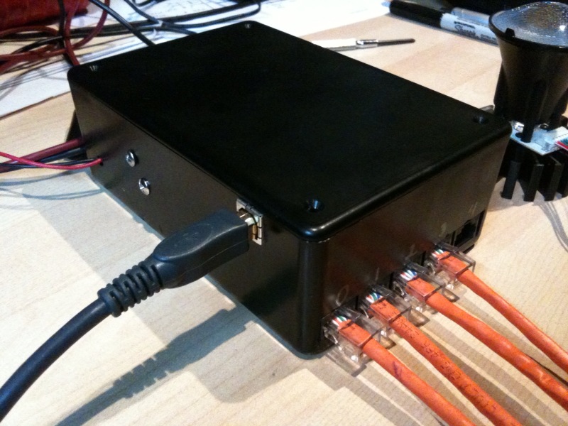
The LM3402 spec sheet indicates that the LED "can be far away (several inches or more) from the LM3402/HV, or on a separate PCB connected by a wiring harness." I am unsure of how long such a wiring harness could be. After testing, I opted for a central controller connected by Cat-5 to several lights on the ceiling. I can see or measure by oscilloscope no difference when the LEDs are wired with few inches of cable or ~30ft of Cat-5 cable.
Besides being convenient, I reason that Cat-5 cable should have minimal capacitance, and is designed for high frequency use. At the 500kHz switching rate I am using, I believe that a twisted pair will reduce the produced electromagnetic radiation.
According to this wire gauge table, 24 AWG wire can carry 0.577A. This rating is for a single conductor, and I am unsure how much a multi-conductor Cat-5 cable should be de-rated. In any case, I certainly observe no heating, and would expect the greatest concern of long runs to be voltage drop, which would limit the maximum current if the LED forward voltage were near the supply voltage. At 500mA, 30 feet of 24AWG should drop around 0.8V. The maximum forward voltage of the Atlas LED is 9V, making a 12V supply entirely sufficient.
Installation & Application
This project is a continuation of a longer-term goal of interesting and useful lighting for my multi-purpose living room. This room is used for just about everything: talking, music, movies, reading, relaxing, and, sometimes, dancing. The system should be flexible to meet (or set) varied moods and purposes. At times, I'd like bright, focused light (esp. for reading). Other times, I'd like to be able to dim to low levels without turning the room orange, as dimmed halogens tend do. When I'm feeling bored with the decorations, subtle (or bold!) colors are fun. I don't necessarily want the same level of illumination or color throughout the room. High speed color changes are most interesting for parties. Perhaps my greatest constraint is that I'd like all of this to be easily programmable, and not fixed to a particular hardware setup.
The lights are currently fitted with 15-degree lenses pointed at the floor. This provides a nice light with little glare. Color temperature is easily adjusted to something warm by reducing the blue component. I have intermittently tested more diffuse lenses to illuminate the ceiling as well, but end up staying with the 15-degree beam. I prefer the good separation of colors, especially for during parties. For greater illumination, rather than using different lenses, I expect I will instead add LEDs for the ceiling, as separate channels, or in series with the existing lamps.
Currently, the ceiling is illuminated when needed with separate halogen spotlights. Eventually, I may augment substitute high power white LEDs instead of halogen lamps for high illumination earlier in the evening. While "white" is easily achieved with the RGB LEDs, their ability to render accurate colors on reflective surfaces is not perfect. That is, they have a poor color rendering index. This happens to be particularly noticeable with my (as yet unsolved) Rubik's cube: red and orange squares are indistinguishable under the LED lighting. White LEDs should produce a better color spectrum.
Firmware and Software
- main.c, main.h, main.hex
- this code is written for a 16f887 PIC. It is targetted for the open-source compiler SDCC.
- libftdi.py
- A CTYPES interface to the libFTDI
library for FTDI chips.
Since the previous LED controller project, I've also fixed some software communications bugs, and now can easily send ~200 color updates per second--much faster than actually visible, and faster than I care to optimize further. - ledcomm.py
- A library for communications with the LED driver board by USB.
- color.py
- A simple class for color manuipulation.
- ledcontrol.py
- The main executable for handling color schemes. I typically run this in an interactive python shell.
Last Modified: 16 Apr 2010